How to Wire a 4~20mA Pressure Sensor: Precautions and Common Troubleshooting
Publication date:2026-10-13 00:18
Pressure sensors output analog signals, most commonly with a two-wire 4-20mA output; there is also a four-wire type (relatively rare). Below, let us learn about the two-wire 4-20mA output wiring of pressure sensors, precautions, and common troubleshooting.
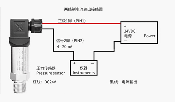
I. Two-Wire 4-20mA Output Wiring
Wiring analysis: The red wire (or marked +) connects to the positive pole of the power supply (+24V); the black wire (or marked -) connects to the positive current input terminal of the signal receiving device (such as the AI module of a PLC). The negative current input terminal (or common terminal COM) of the signal receiving device connects back to the negative pole of the power supply (0V).
Working mode: The internal circuit of the transmitter adjusts its own impedance, so that the loop current varies between 4mA (corresponding to zero pressure/lower limit of the range) and 20mA (corresponding to full-scale pressure). The power supply powers the entire pressure transmitter through the signal line.
Advantages: strong anti-interference capability (current signal), simple wiring (only two wires needed), capable of long-distance transmission, and intrinsic safety design is easier to achieve.
II. Precautions:
1. Supply voltage: the standard is 24V DC (usually in the range of 9-36V DC); make sure the power supply is powerful enough to drive the pressure sensor and the loop load.
2. Polarity and reverse-connection protection: reverse connection may damage the pressure sensor! Be sure to check the wire sequence before the first power-on.
3. Load impedance: the total loop impedance must satisfy: supply voltage ≥ (load impedance × 0.02A) + minimum operating voltage of the pressure sensor; typical load: a PLC's 250Ωinput resistance (corresponding to a 1-5V voltage signal).
4. Shielding and grounding: for long-distance transmission, use shielded twisted-pair cable, with the shield grounded at a single point (usually on the control cabinet side); avoid routing parallel to power cables to reduce interference.
III. Common Troubleshooting
Symptom Possible cause Solution
Output is always 0mA Power not connected / reverse-connected Check power polarity and voltage
Output is fixed at the maximum value (20mA) Sensor damaged by overvoltage or wiring short circuit Disconnect the load and test the sensor
Large signal fluctuation Electromagnetic interference or poor grounding Check shield grounding
Reading is lower than the actual value Load impedance too high or insufficient power supply Reduce the impedance or increase the supply voltage