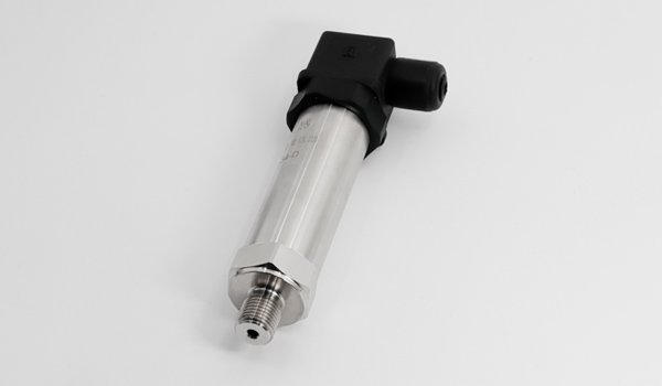
How Does a Diffused Silicon Pressure Sensor Work? Its Working Principle
Publication date:2026-10-13 00:19
The working principle of the diffused silicon pressure sensoris based on the piezoresistive effect of monocrystalline silicon on the silicon diaphragm, converting the resistance change caused by pressure into an electrical signal output through a Wheatstone bridge. To protect the fragile silicon diaphragm, industrial diffused silicon pressure sensors usually adopt an isolation diaphragm structure. Pressure is transmitted through a corrosion-resistant isolation diaphragm (such as 316L stainless steel, Hastelloy, etc.); the sealed cavity between the diaphragms is filled with silicone oil or another transmission fluid, transmitting the pressure without loss to the internal silicon pressure-sensing diaphragm.
1. Core element: silicon diaphragm
The core of the sensor is a very thin (micron-level) monocrystalline silicon diaphragm (pressure-sensing diaphragm), usually fabricated on a silicon base using micromachining technology (MEMS).
2. Piezoresistors:
At specific positions on the silicon diaphragm (usually at the edge where stress is greatest), four highly consistent piezoresistors are fabricated using semiconductor doping processes (such as ion implantation or diffusion).
3. Wheatstone bridge:
These four piezoresistors are arranged on the silicon diaphragm in specific directions (two along the radial direction and two along the tangential direction) and are connected into a Wheatstone bridge circuit. In the no-pressure state, the bridge is in a balanced state (output voltage is zero).
4. Piezoresistive effect:
Core principle: When pressure (P) is applied to one side of the diaphragm, the diaphragm undergoes a slight deformation (bending).
Resistance change: Silicon material has a significant piezoresistive effect. The deformation causes strain (tension or compression) in the silicon lattice structure, thereby changing the resistance value of the piezoresistors on the diaphragm (ΔR). Usually, when the center of the diaphragm is under pressure, the two edge resistors are stretched and their resistance increases (R↑), while the other two are compressed and their resistance decreases (R↓).
5. Bridge imbalance and output:
The measured pressure is transmitted to the silicon wafer through the isolation diaphragm and silicone oil; the change in resistance (ΔR) disrupts the balance of the Wheatstone bridge. The output terminals of the bridge (usually called +Out and -Out or Sig+ and Sig-) produce a tiny differential voltage signal (mV level) proportional to the applied pressure.
6. Signal processing (usually inside the transmitter):
This weak mV signal is processed by a signal conditioning circuit inside or outside the sensor (amplification, linearization, temperature compensation, standardization), and finally converted into an industrial standard signal (such as a 4-20mA current signal, 0-5V/0-10V voltage signal, digital signal, etc.), for easy reading by subsequent PLCs, DCSs or display instruments.
7. Temperature compensation:
The piezoresistive effect and the resistance of silicon are themselves sensitive to temperature. Therefore, a temperature-sensitive element (such as a thermistor) is integrated inside the sensor, and compensation circuits or software algorithms are used to correct errors caused by temperature drift.
Summary of the principle chain: pressure (P) -> pressure-sensing diaphragm deforms -> piezoresistor strain -> resistance change (ΔR) -> Wheatstone bridge imbalance -> generates differential voltage (ΔV) -> signal conditioning -> standard output signal